ตำรายาของประเทศไทย
Thai Pharmacopoeia
สำนักยาและวัตถุเสพติด กรมวิทยาศาสตร์การแพทย์ กระทรวงสาธารณสุข
Bureau of Drug and Narcotic, Department of Medical Sciences, Ministry of Public Healthสำนักยาและวัตถุเสพติด กรมวิทยาศาสตร์การแพทย์ กระทรวงสาธารณสุข
Bureau of Drug and Narcotic, Department of Medical Sciences, Ministry of Public Health4.10 DETERMINATION OF VISCOSITY
Viscosity is a property of liquids that is closely related to the resistance to flow. It is defined in terms of the force required to move one plane surface continuously past another under specified steady-state conditions when the space between is filled by the liquid in question. In other words it is the shear stress divided by the rate of shear strain. The unit1 is the pascal second (Pa.s), viscosities commonly encountered represent fractions of the pascal second, so that the millipascal second (mPa.s) proves to be the more convenient unit. The specifying of temperature is important because viscosity changes with temperature; in general, viscosity decreases as temperature is raised. While on the absolute scale viscosity is measured in pascal second or millipascal second, for convenience, the kinematic scale, in which the units are square centimetres per second (cm2 .s–1) and square millimetres per second (mm2 .s–1), commonly is used. To obtain the kinematic viscosity from the absolute viscosity, the latter is divided by the density of the liquid at the same temperature, i.e. kinematic viscosity = (absolute viscosity)/(density). The sizes of the units are such that viscosities in the ordinary ranges are conveniently expressed in square millimetres per second. The approximate viscosity in square millimetres per second at room temperature of ether is 0.2; of water, 1; of kerosene, 2.5; of liquid paraffin, 20 to 70; and of honey, 10,000.
Absolute viscosity can be measured directly if accurate dimensions of the measuring instruments are known, but it is more common practice to calibrate the instrument with a liquid of known viscosity and to determine the viscosity of the unknown fluid by comparison with that of the known.
Many substances, such as the gums employed in pharmacy, have variable viscosity, and most of them are less resistant to flow at higher flow rates. In such cases, a given set of conditions is selected for measurement, and the measurement obtained is considered to be an apparent viscosity. Since a change in the conditions of measurement would yield a different value for the apparent viscosity of such substances, the instrument dimensions and conditions for measurement must be closely adhered to by the operator.
1In the centimetre-gram-second (CGS) system, the unit of absolute viscosity is the poise or the centipoise and the unit of kinematic viscosity is the stoke or the centistoke.
Unit Equivalence
SI Unit CGS Unit
10–1 Pa.s = 1 poise
1 mPa.s = 1 centipoise
1 cm2 .s–1 = 1 stoke
1 mm2 .s–1 = l centistoke
Method I
APPARATUS The apparatus consists of a glass U-tube viscometer (Fig. 1) made of clear borosilicate glass and constructed in accordance with the dimensions shown in the figure and in Table 1; the monograph states the size of a viscometer to be used.
PROCEDURE Fill the viscometer with the test liquid through tube L to slightly above the mark G, using a long pipette to minimize wetting the tube above the mark. Place the tube vertically in a water-bath and when it has attained the specified temperature, adjust the volume of the liquid so that the bottom of the meniscus settles at the mark G. Suck or blow the liquid to a point about 5 mm above the mark E. After releasing pressure or suction, measure the time taken for the bottom of the meniscus to fall from the top edge of mark E to the top edge of mark F.
Calculate, as required, either the kinematic viscosity (ν) in square millimetres per second (mm2 .s−1 ) from the equation:
ν = Kt,
or the absolute viscosity (η) in pascal seconds (Pa.s) from the equation:
η = Kρt,
where t = time in seconds for the meniscus to fall from E to F, and
ρ = mass per volume (g.cm–3).
The constant (K) of the instrument is determined using the appropriate reference liquid for viscometers.
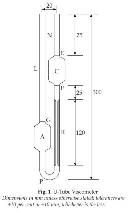
Table 1 U-Tube Viscometer-Dimensions
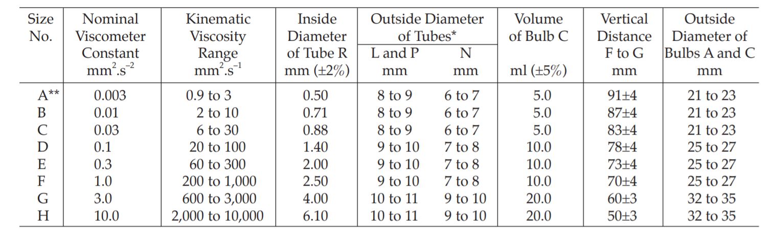
*Use 1 to 1.25 mm wall tubing for L, N, and P.
**300 s minimum flow times; 200 s minimum flow time for all other sizes.
Method II
APPARATUS The apparatus consists of a glass suspended-level viscometer (Fig. 2) made of clear borosilicate glass and constructed in accordance with the dimensions shown in Table 2; the size to be used is specified in the monograph.
PROCEDURE Fill the viscometer through tube L with a sufficient quantity of the test liquid to fill bulb A but ensuring that the level of liquid in bulb B is below the exit to ventilation tube M. After the tube has been placed vertically in the bath and has attained the specified temperature, close tube M and apply suction to tube N until the liquid reaches a level about 8 mm above mark E. Hold the liquid at this level by closing tube N and open tube M. When the liquid is clear of the capillary end of tube N and the lower end of tube M, open tube N. Measure the time taken for the bottom of the meniscus to fall from the top edge of mark E to the top edge of mark F.
If the end of tube M becomes blocked by the liquid at any time while the flow time is being measured, the determination must be repeated.
Calculate the kinematic viscosity (ν) in square millimetres per second (mm2 .s–1) from the equation:
ν = Kt,
where t = time in seconds for the meniscus to fall from E to F.
The constant (K) of the instrument is determined using the appropriate reference liquid for viscometers.
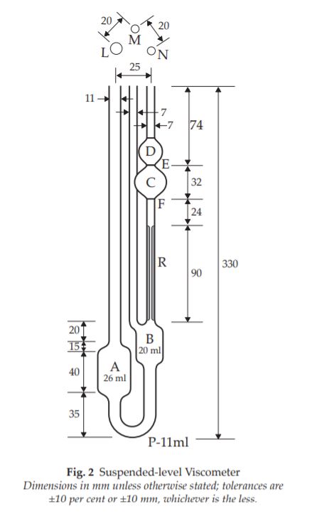
Table 2 Suspended-level Viscometer-Dimensions
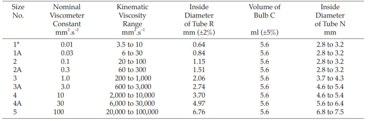
*350 s minimum flow time; 200 s minimum flow time for all other sizes.
Method III
APPARATUS The apparatus consists of a fallingsphere viscometer. It comprises the following parts:
(a) A bath constructed of clear glass or having clear glass windows which allow the observation of all the graduations on the fall tube. It is provided with a cover bared to accommodate the thermometer, a tube to hold the balls to be used in the test, a stirring device, and the fall tube. The bath is filled to at least 30 mm above the topmost graduation of the fall tube, and the temperature in the bath is maintained between 19.9º and 20.1º.
(b) A fall tube (see Fig. 3) of nominal internal diameter 25 mm and between 317 and 323 mm long, made of clear glass. The tube is etched with six fine marks at the distances given in the figure, measured from a line 30 mm from the closed end. The marks encircle the tube at right-angles to the axis and no interval shall be in error by more than 0.5 mm. The numbers are etched below the lines. The tube is fitted with a bored plug of inert non-absorbent material carrying a glass delivery tube with a funnel top, or with a glass insert adjusted so that the lower end of the delivery tube is 5 mm above
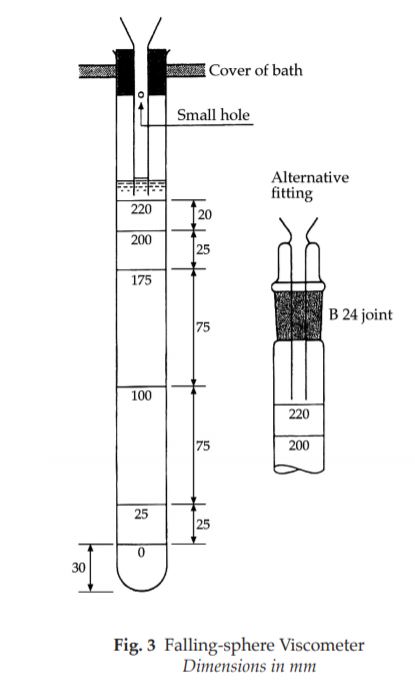
the topmost graduation mark; an internal diameter of 2.5 mm is suitable.
(c) A suitable thermometer of the “total immersion” type.
(d) A sphere of steel or other suitable material 1.59 mm in diameter. Steel spheres should be kept in liquid paraffin or other suitable materials to prevent rusting.
PROCEDURE Fill the fall tube with the test liquid to about 10 mm above the 220-mm mark, place vertically in the bath, and allow to stand for air bubbles to clear and for temperature equilibrium to be attained. Clean the sphere, immerse it in a portion of the test liquid maintained at a temperature, between 19.9º and 20.1º, and when it is at this temperature, introduce it, without wiping, into the delivery tube. Observe the time for the lowest part of the sphere to pass through the planes of the tops of the 175-mm mark and the 25-mm mark, using a telescope or other suitable device to avoid errors due to parallax. The average of three readings concordant to within 0.5 per cent is taken as the time of fall.
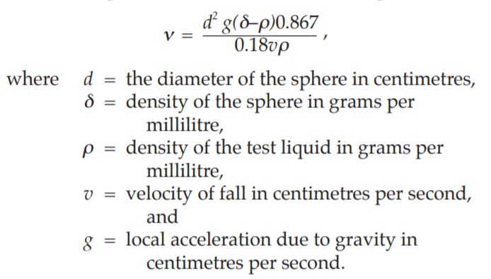
Calculate the kinematic viscosity (ν) in square millimetres per second (mm2 .s–1) from the equation:
Method IV (for non-newtonian systems)
Operate a rotating cylinder viscometer in accordance with the manufacturer’s instructions. The temperature and the angular velocity or shear rate, at which the dermination should be carried out, are indicated in the monograph.
Calculate the absolute viscosity (η) in pascal seconds (Pa.s) from the equation:
η = KL/ω,
where L = the angular momentum in newton metres, and
ω = the angular speed in radians per second.
The constant (K) of the instrument is determined using the appropriate reference liquid for viscometers, or by reference to tables supplied by the instrument manufacturers giving the constants in relation to the surface area of the cylinders used and their speed of rotation.