ตำรายาของประเทศไทย
Thai Pharmacopoeia
สำนักยาและวัตถุเสพติด กรมวิทยาศาสตร์การแพทย์ กระทรวงสาธารณสุข
Bureau of Drug and Narcotic, Department of Medical Sciences, Ministry of Public Healthสำนักยาและวัตถุเสพติด กรมวิทยาศาสตร์การแพทย์ กระทรวงสาธารณสุข
Bureau of Drug and Narcotic, Department of Medical Sciences, Ministry of Public Health4.34 POWDER FLOW
The widespread use of powders in the pharmaceutical industry has generated a variety of methods for characterizing powder flow. Not surprisingly, scores of references appear in the pharmaceutical literature, attempting to correlate the various measures of powder flow to manufacturing properties. The development of such a variety of test methods was inevitable; powder behavior is multifaceted and thus complicates the effort to characterize powder flow.
The purpose of this appendix is to review the methods for characterizing powder flow that have appeared most frequently in the pharmaceutical literature. In addition, while it is clear that no single and simple test method can adequately characterize the flow properties of pharmaceutical powders, this chapter proposes the standardization of test methods that may be valuable during pharmaceutical development.
Four commonly reported methods for testing powder flow are:
– angle of repose,
– compressibility index or Hausner ratio,
– flow rate through an orifice, and
– shear cell.
In addition, numerous variations of each of these basic methods are available. Given the number of test methods and variations, standardizing the test methodology, where possible, would be advantageous.
With this goal in mind, the most frequently used methods are discussed below. Important experimental considerations are identified and recommendations are made regarding standardization of the methods. In general, any method of measuring powder flow must be practical, useful, reproducible and sensitive, and must yield meaningful results. It bears repeating that no simple powder flow method will adequately or completely characterize the wide range of flow properties experienced in the pharmaceutical industry. An appropriate strategy may well be the use of multiple standardized test methods to characterize the various aspects of powder flow as needed by the pharmaceutical scientist.
Angle of Repose
The angle of repose has been used in several branches of science to characterize the flow properties of solids. Angle of repose is a characteristic related to interparticulate friction, or resistance to movement between particles. Angle of repose test results are reported to be very dependent upon the method used. Experimental difficulties arise due to segregation of material and consolidation or aeration of the powder as the cone is formed. Despite its difficulties, the method continues to be used in the pharmaceutical industry, and a number of examples demonstrating its value in predicting manufacturing problems appear in the literature.
The angle of repose is the constant, three-dimensional angle (relative to the horizontal base) assumed by a cone-like pile of material formed by any of several different methods, described briefly below.
BASIC METHODS FOR ANGLE OF REPOSE A variety of angle of repose test methods are described in the literature. The most common methods for determining the static angle of repose can be classified based on 2 important experimental variables:
– the height of the “funnel” through which the powder passes may be fixed relative to the base, or the height may be varied as the pile forms;
– the base upon which the pile forms may be of fixed diameter or the diameter of the powder cone may be allowed to vary as the pile forms.
VARIATIONS IN ANGLE OF REPOSE METHODS Variations of the above methods have also been used to some extent in the pharmaceutical literature:
– drained angle of repose is determined by allowing an excess quantity of material positioned above a fixed diameter base to “drain” from the container. Formation of a cone of powder on the fixed diameter base allows determination of the drained angle of repose;
– dynamic angle of repose is determined by filling a cylinder (with a clear, flat cover on one end) and rotating it at a specified speed. The dynamic angle of repose is the angle (relative to the horizontal) formed by the flowing powder. The internal angle of kinetic friction is defined by the plane separating those particles sliding down the top layer of the powder and those particles that are rotating with the drum (with roughened surface).
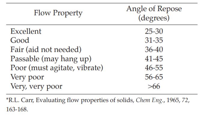
GENERAL SCALE OF FLOWABILITY FOR ANGLE OF REPOSE While there is some variation in the qualitative description of powder flow using the angle of repose, much of the pharmaceutical literature appears to be consistent with the classification by Carr (Table 1). There are examples in the literature of formulations with an angle of repose in the range of 40 to 50 degrees that manufactured satisfactorily. When the angle of repose exceeds 50 degrees, the flow is rarely acceptable for manufacturing purposes.
Table 1 Flow Properties and Corresponding Angles of Repose*
EXPERIMENTAL CONSIDERATIONS FOR ANGLE OF REPOSE Angle of repose is not an intrinsic property of the powder, that is to say, it is very much dependent upon the method used to form the cone of powder. On this subject, the existing literature raises these important considerations:
– the peak of the cone of powder can be distorted by the impact of powder from above. By carefully building the powder cone, the distortion caused by impact can be minimized;
– the nature of the base upon which the powder cone is formed influences the angle of repose. It is recommended that the powder cone be formed on a “common base”, which can be achieved by forming the cone of powder on a layer of powder. This can be done by using a base of fixed diameter with a protruding outer edge to retain a layer of powder upon which the cone is formed.
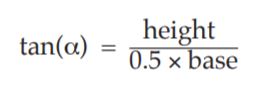
RECOMMENDED PROCEDURE FOR ANGLE OF REPOSE Form the angle of repose on a fixed base with a retaining lip to retain a layer of powder on the base. The base must be free of vibration. Vary the height of the funnel to carefully build up a symmetrical cone of powder. Care must be taken to prevent vibration as the funnel is moved. The funnel height is maintained at approximately 2 to 4 cm from the top of the powder pile as it is being formed in order to minimize the impact of falling powder on the tip of the cone. If a symmetrical cone of powder cannot be successfully or reproducibly prepared, this method is not appropriate. Determine the angle of repose by measuring the height of the cone of powder and calculating the angle of repose, α, from the following equation:
Compressibility Index and Hausner Ratio
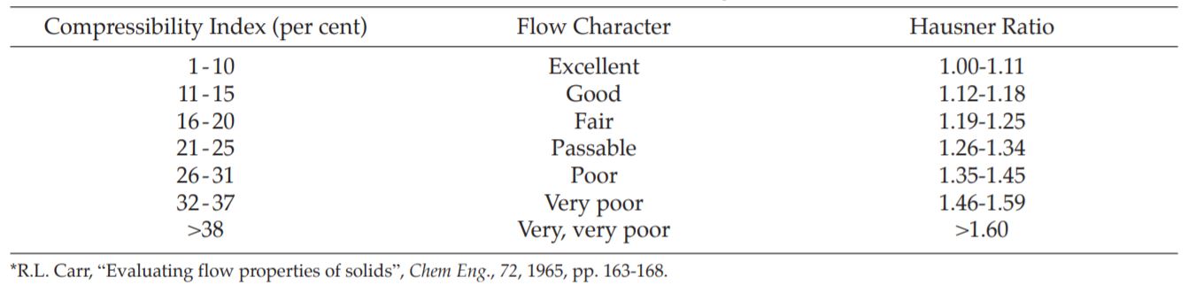
In recent years the compressibility index and the closely related Hausner ratio have become the simple, fast, and popular methods of predicting powder flow characteristics. The compressibility index has been proposed as an indirect measure of bulk density, size and shape, surface area, moisture content, and cohesiveness of materials, because all of these can influence the observed compressibility index. The compressibility index and the Hausner ratio are determined by measuring both the bulk volume and tapped volume of a powder.
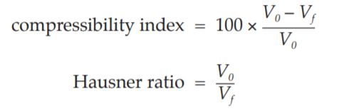
BASIC METHODS FOR COMPRESSIBILITY INDEX AND HAUSNER RATIO While there are some variations in the method of determining the compressibility index and Hausner ratio, the basic procedure is to measure the unsettled apparent volume, (V0), and the final tapped volume, (Vf ), of the powder after tapping the material until no further volume changes occur. The compressibility index and the Hausner ratio are calculated as follows:
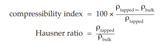
Alternatively, the compressibility index and Hausner ratio may be calculated using measured values of bulk density (ρbulk) and tapped density (ρtapped) as follows:
In a variation of these methods, the rate of consolidation is sometimes measured rather than, or in addition to, the change in volume that occurs on tapping. For the compressibility index and the Hausner ratio, the generally accepted scale of flow ability is given in Table 2.
EXPERIMENTAL CONSIDERATIONS FOR THE COMPRESSIBILITY INDEX AND HAUSNER RATIO Compressibility index and Hausner ratio are not intrinsic properties of the powder, that is to say, they are dependent upon the methodology used. The existing literature points out several important considerations affecting the determination of the unsettled apparent volume, V0, of the final tapped volume, Vf , of the bulk density, ρbulk, and of the tapped density, ρtapped:
– the diameter of the cylinder used,
– the number of times the powder is tapped to achieve the tapped density,
– the mass of material used in the test, and
– rotation of the sample during tapping.
RECOMMENDED PROCEDURE FOR COMPRESSIBILITY INDEX AND HAUSNER RATIO Use a 250 ml volumetric cylinder with a test sample weight of 100 g. Smaller amounts and volumes may be used, but variations in the method must be described with the results. An average of three determinations is recommended.
Flow Through an Orifice
The flow rate of a material depends upon many factors, some of which are particle-related and some related to the process. Monitoring the rate of flow of material through an orifice has been proposed as a better measure of powder flowability. Of particular significance is the utility of monitoring flow continuously, since pulsating flow patterns have been observed even for free-flowing materials. Changes in flow rate as the container empties can also be observed. Empirical equations relating flow rate to the diameter of the opening, particle size, and particle density have been determined. However, determining the flow rate through an orifice is useful only with free-flowing materials.
The flow rate through an orifice is generally measured as the mass per time flowing from any of a number of types of containers (cylinders, funnels, hoppers). Measurement of the flow rate can be in discrete increments or continuous.
BASIC METHODS FOR FLOW THROUGH AN ORIFICE There are a variety of methods described in the literature. The most common for determining the flow rate through an orifice can be classified based on three important experimental variables:
– the type of container used to contain the powder. Common containers are cylinders, funnels, and hoppers from production equipment;
– the size and shape of the orifice used. The orifice diameter and shape are critical factors in determining powder flow rate;
– the method of measuring powder flow rate. Flow rate can be measured continuously using an electronic balance with some sort of recording device (strip chart recorder, computer). It can also be measured in discrete samples (for example, the time it takes for 100 g of powder to pass through the orifice to the nearest tenth of a second or the amount of powder passing through the orifice in 10 to the nearest tenth of a gram).
VARIATIONS IN METHODS FOR FLOW THROUGH AN ORIFICE Either mass flow rate or volume flow rate can be determined. Mass flow rate is the easier of the methods, but it biases the results in favour of high-density materials. Since die fill is volumetric, determining volume flow rate may be preferable. A vibrator is occasionally attached to facilitate flow from the container, however, this appears to complicate interpretation of results. A moving orifice device has been proposed to more closely simulate rotary press conditions. The minimum diameter orifice through which powder flows can also be identified.
GENERAL SCALE OF FLOWABILITY FOR FLOW THROUGH AN ORIFICE No general scale is available because flow rate is critically dependent on the method used to measure it. Comparison between published results is difficult.
EXPERIMENTAL CONSIDERATIONS FOR FLOW THROUGH AN ORIFICE Flow rate through an orifice is not an intrinsic property of the powder. It is very much dependent upon the methodology used. The existing literature points out several important considerations affecting these methods:
– the diameter and shape of the orifice,
– the type of container material (metal, glass, plastic),
– the diameter and height of the powder bed.
Table 2 Scale of Flowability*
RECOMMENDED PROCEDURE FOR FLOW THROUGH AN ORIFICE Flow rate through an orifice can be used only for materials that have some capacity to flow. It is not useful for cohesive materials. Provided that the height of the powder bed (the 'head' of powder) is much more than the diameter of the orifice, the flow rate is virtually independent of the powder head. It is advisable to use a cylinder as the container, because the walls of the container must have little effect on flow. This configuration results in flow rate being determined by the movement of powder over powder, rather than powder along the wall of the container. Powder flow rate often increases when the height of the powder column is less than twice the diameter of the column. The orifice must be circular and the cylinder must be free of vibration. General guidelines for dimensions of the cylinder are as follows:
– diameter of the opening more than 6 times the diameter of the particles,
– diameter of the cylinder more than twice the diameter of the opening.
Use of a hopper as the container may be appropriate and representative of flow in a production situation. It is not advisable to use a funnel, particularly one with a stem, because flow rate will be determined by the size and length of the stem as well as the friction between the stem and the powder. A truncated cone may be appropriate, but flow will be influenced by the powderwall friction coefficient, thus, selection of an appropriate construction material is important.
For the opening in the cylinder, use a flat-faced bottom plate with the option to vary orifice diameter to provide maximum flexibility and better ensure a powder-over-powder flow pattern. Rate measurement can be either discrete or continuous. Continuous measurement using an electronic balance can more effectively detect momentary flow rate variations.
Shear Cell Methods
In an effort to put powder flow studies and hopper design on a more fundamental basis, a variety of powder shear testers and methods that permit more through and precisely defined assessment of powder flow properties have been developed. Shear cell methodology has been used extensively in the study of pharmaceutical materials. From these methods, a wide variety of parameters can be obtained, including the yield loci representing the shear stress-shear strain relationship, the angle of internal friction, the unconfined yield strength, the tensile strength, and a variety of derived parameters such as the flow factor and other flowability indices. Because of the ability to control experimental parameters more precisely, flow properties can also be determined as a function of consolidation load, time, and other environmental conditions. These methods have been successfully used to determine critical hopper and bin parameters.
BASIC METHODS FOR SHEAR CELL One type of shear cell is the cylindrical shear cell which is split horizontally, forming a shear plane between the lower stationary base and the upper moveable portion of the shear cell ring. After powder bed consolidation in the shear cell (using a well-defined procedure), the force necessary to shear the powder bed by moving the upper ring is determined. Annular shear cell designs offer some advantages over the cylindrical shear cell design, including the need for less material. A disadvantage, however, is that because of its design, the powder bed is not sheared as uniformly because material on the outside of the annulus is sheared more than material in the inner region. A third type of shear cell (plate-type) consists of a thin sandwich of powder between a lower stationary rough surface and an upper rough surface that is moveable.
All of the shear cell methods have their advantages and disadvantages, but a detailed review is beyond the scope of this chapter. As with the other methods for characterizing powder flow, many variations are described in the literature. A significant advantage of shear cell methodology in general is a greater degree of experimental control. The methodology generally is rather time-consuming and requires significant amounts of material and a well-trained operator.
RECOMMENDATIONS FOR SHEAR CELL The many existing shear cell configurations and test methods provide a wealth of data and can be used very effectively to characterize powder flow. They are also helpful in the design of equipment such as hoppers and bins. Because of the diversity of available equipment and experimental procedures, no specific recommendations regarding methodology are presented in this appendix. It is recommended that the results of powder flow characterization using shear cell methodology include a complete description of equipment and methodology used.